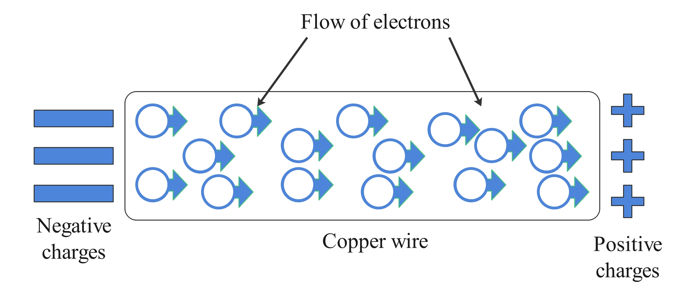
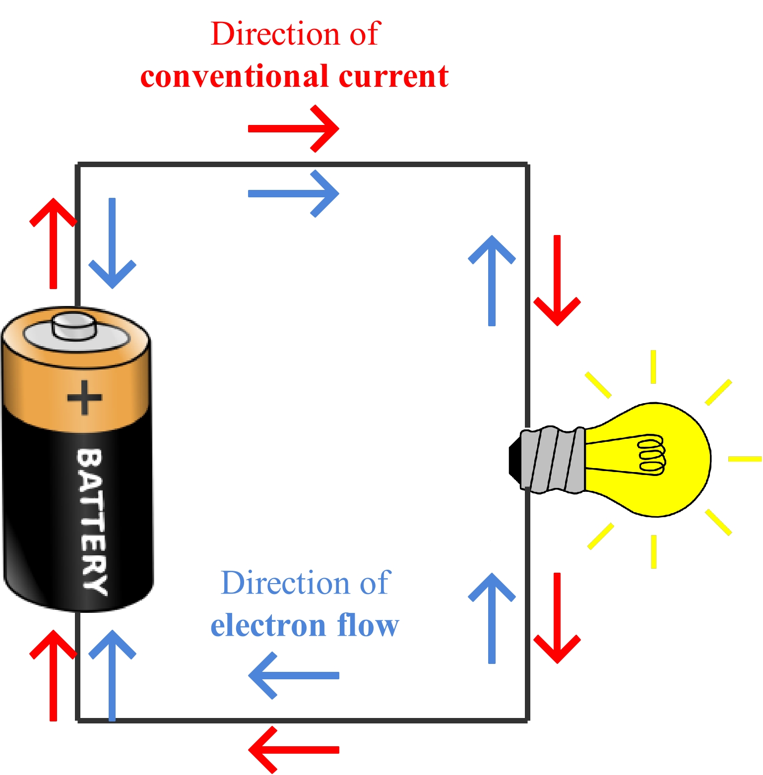
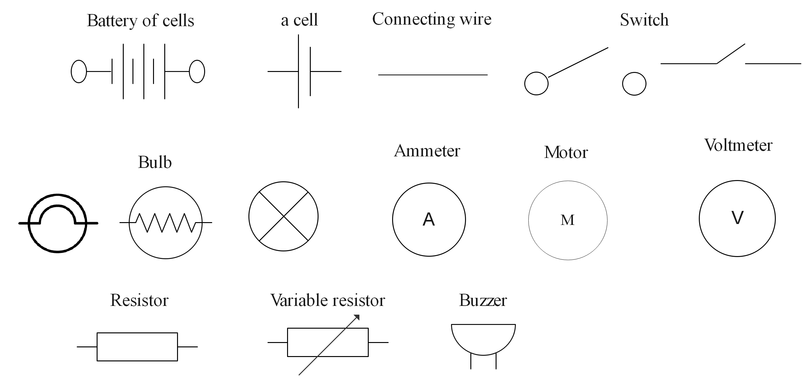
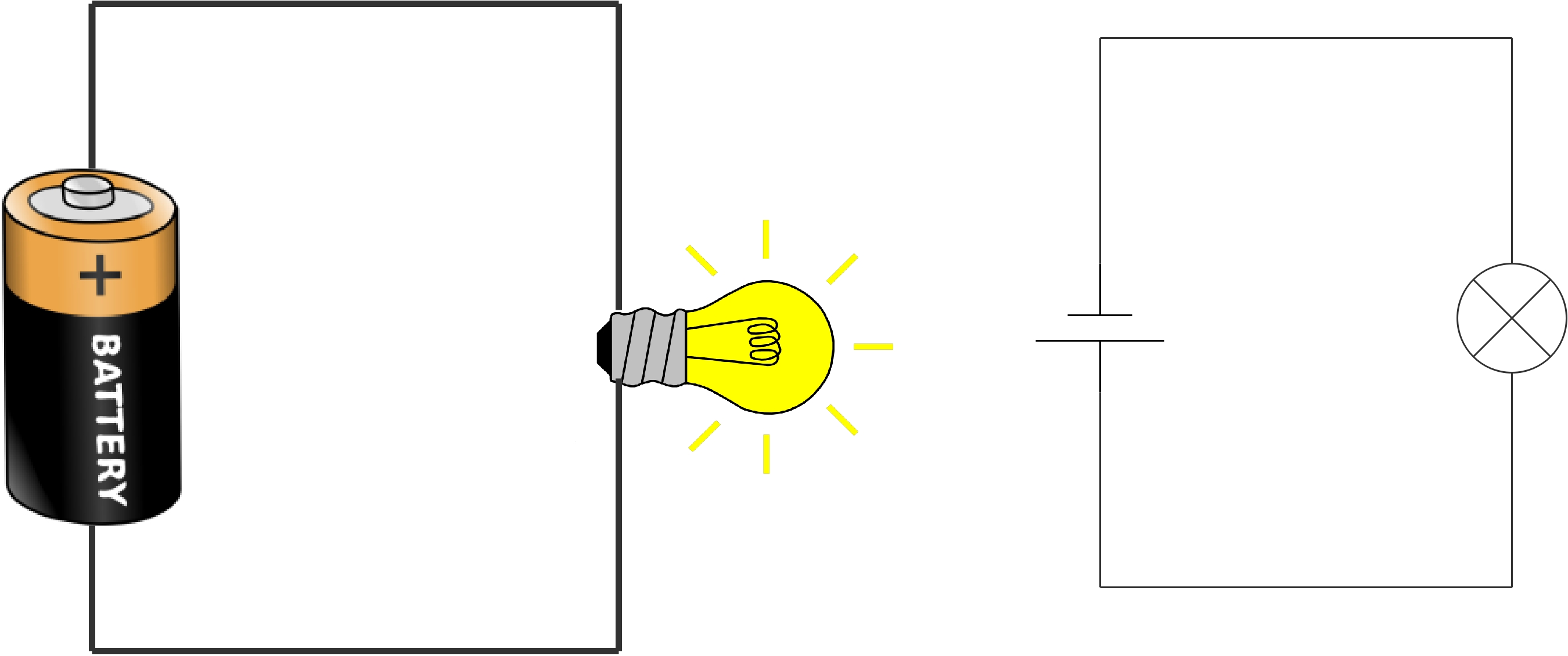
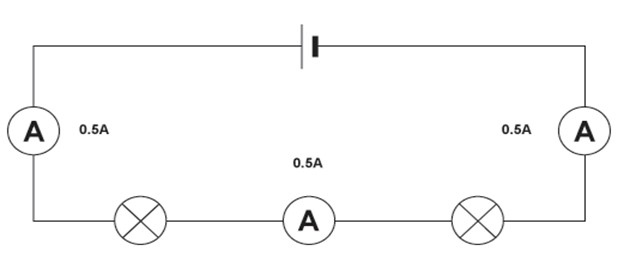
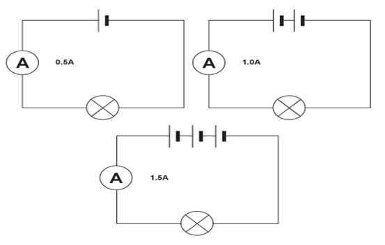
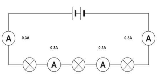
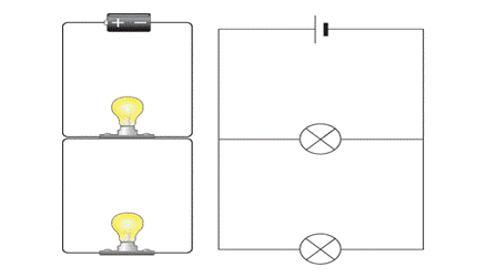
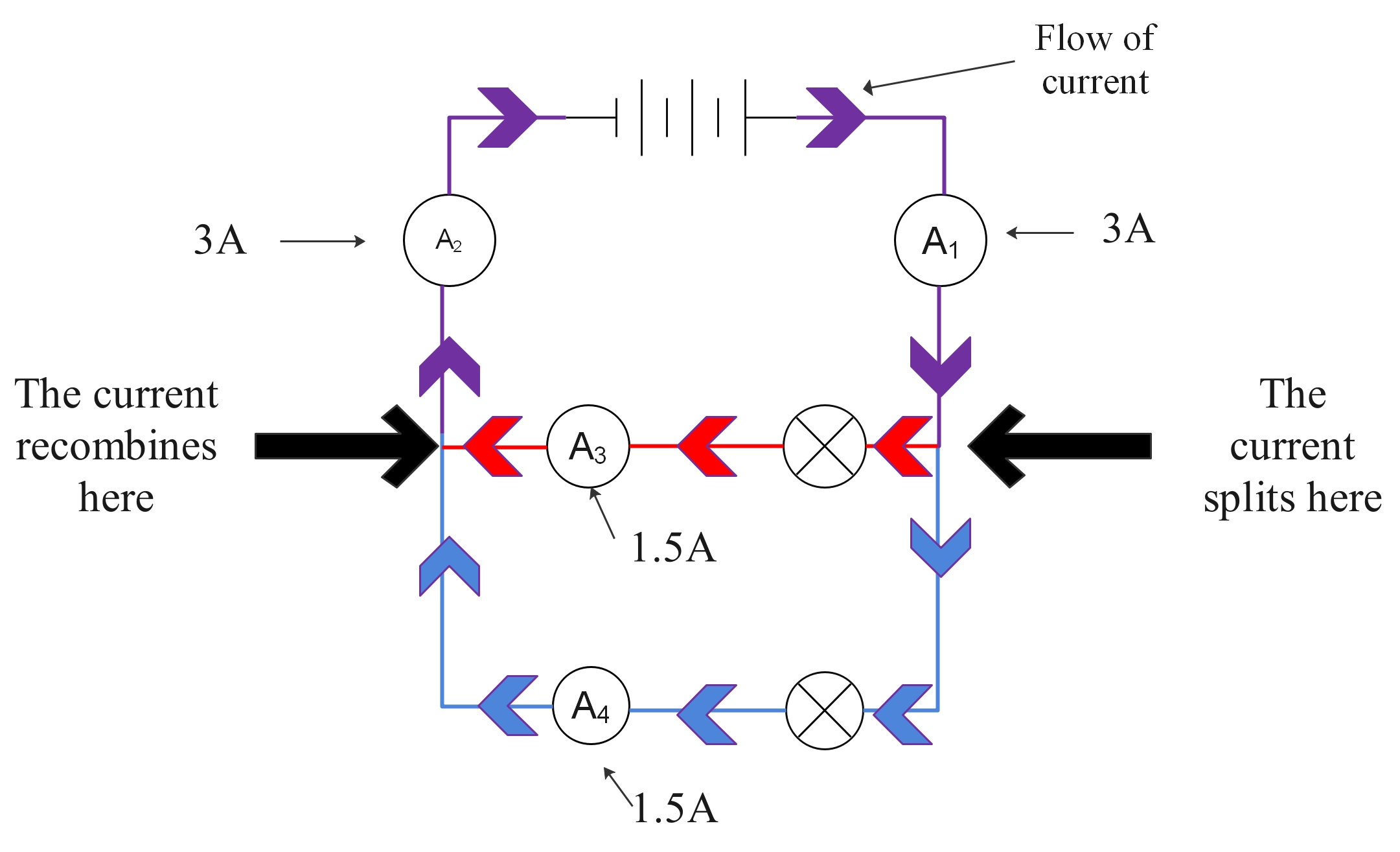
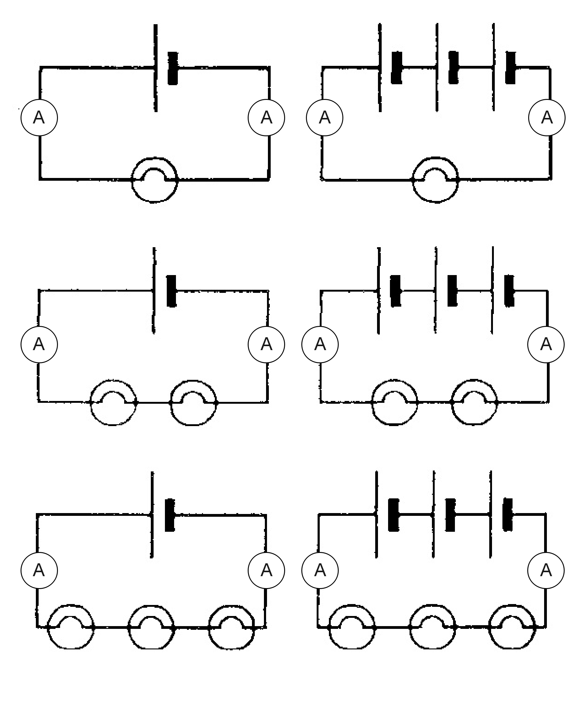
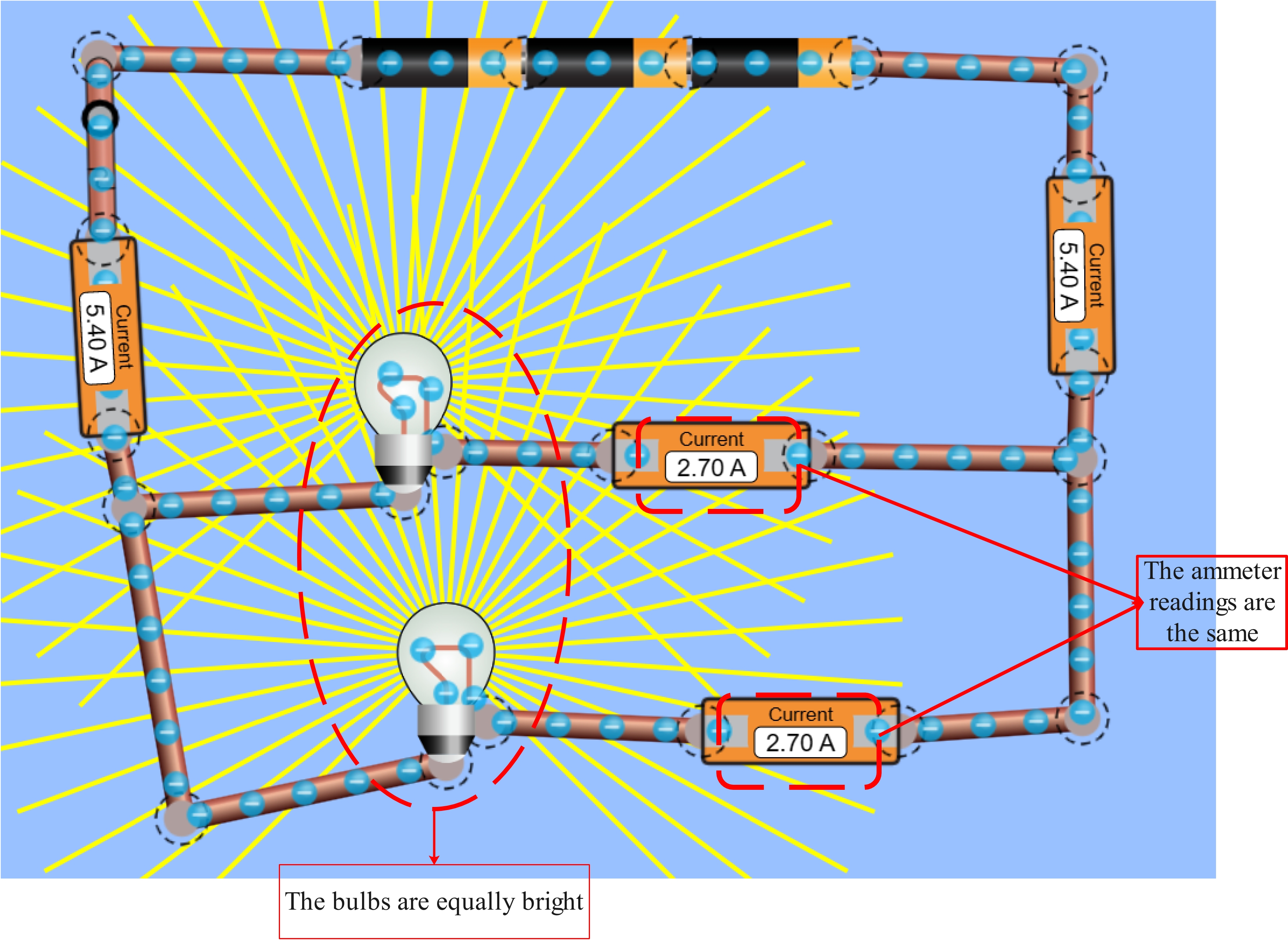
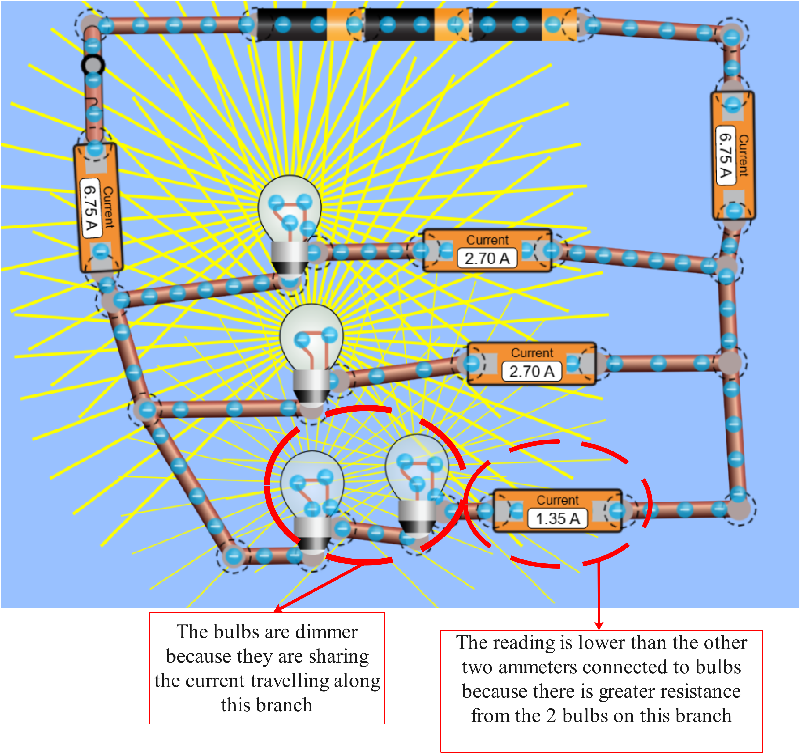
A cell/battery pushes electrons around a circuit. It is a kind of electron pump. This electrical pressure is called electromotive force (e.m.f) and is measured in volts (V).
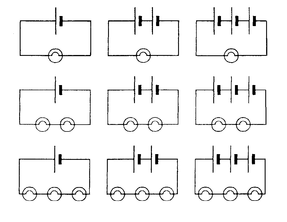
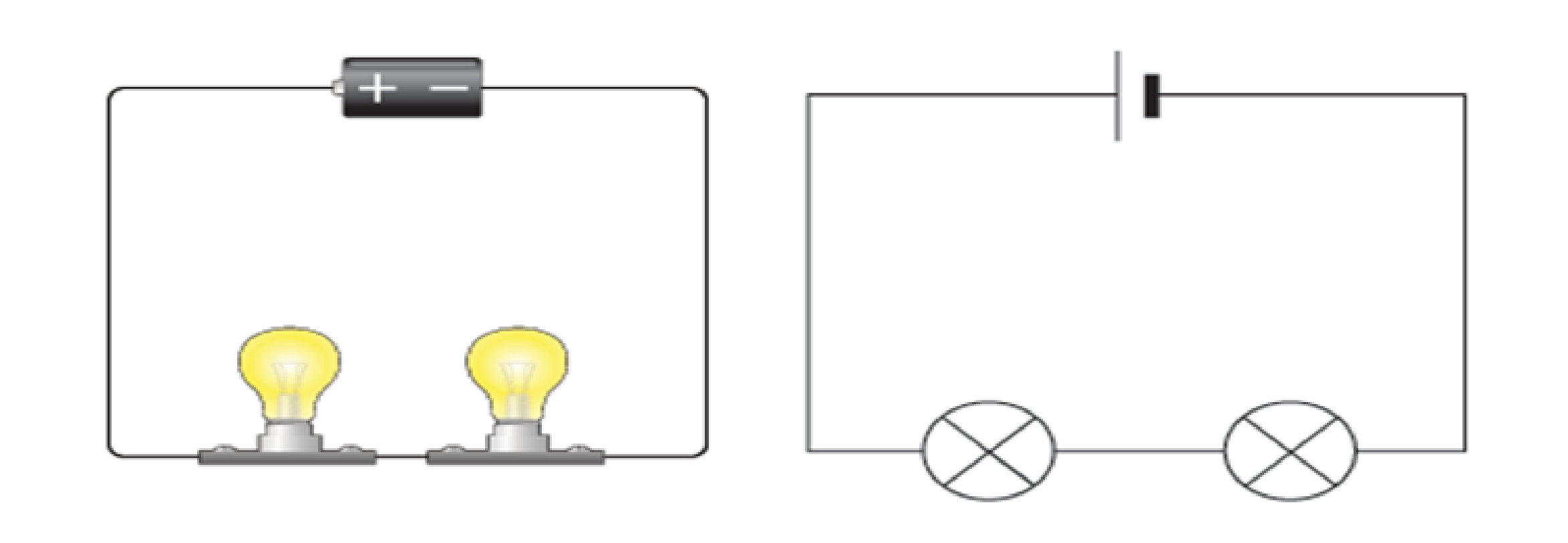
When a cell is connected to a series of bulbs, the e.m.f pushes electrons round the circuit. The energy to do this comes from the chemical energy in the battery. The electrons give up this energy to the thin wires inside the bulb, so they get hot and glow.

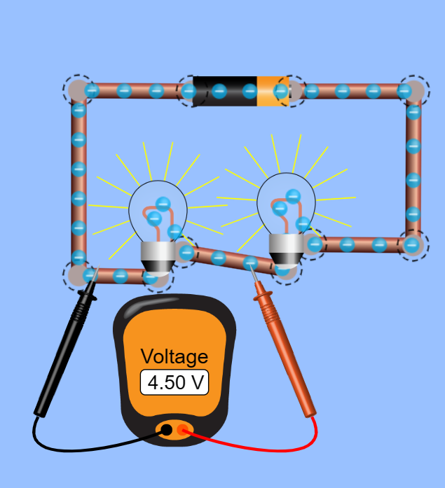
Across each bulb, there is an electrical energy difference called potential difference or voltage. This is measured in volts using a voltmeter.
Current is the number of electrons that happen to be passing through any one point of a circuit at a given time. The higher the current, the more work it can do at the same voltage.
Power = voltage x current. The higher the power, the quicker the rate at which a battery can do work—this relationship shows how voltage and current are both important for working out what a battery is suitable for.
Voltage is measured in volts. The symbol for volts is V. For example, 230V is a bigger voltage than 12V. Voltage is measured using a voltmeter. Some types of voltmeters have a pointer on a dial, but most have a digital readout. To measure the voltage across a component in a circuit, you must connect the voltmeter in parallel with it.
Activity 1:
1. Click on the link below:
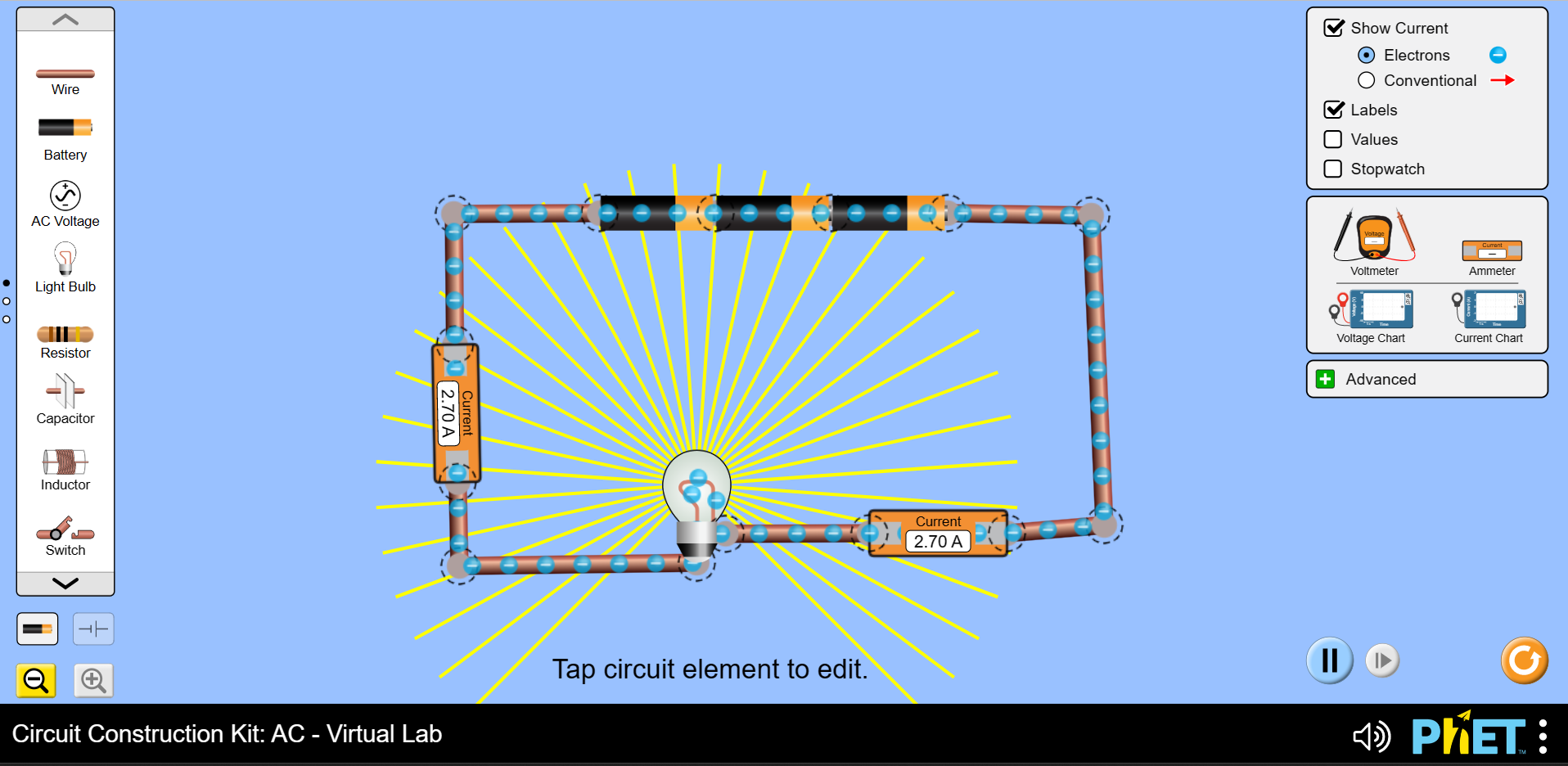
https://phet.colorado.edu/sims/html/circuit-construction-kit-ac-virtual-lab/latest/circuit-construction-kit-ac-virtual-lab_en.html
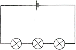
2. Build the circuit shown in the diagram below and measure the voltage of one of the lamps. 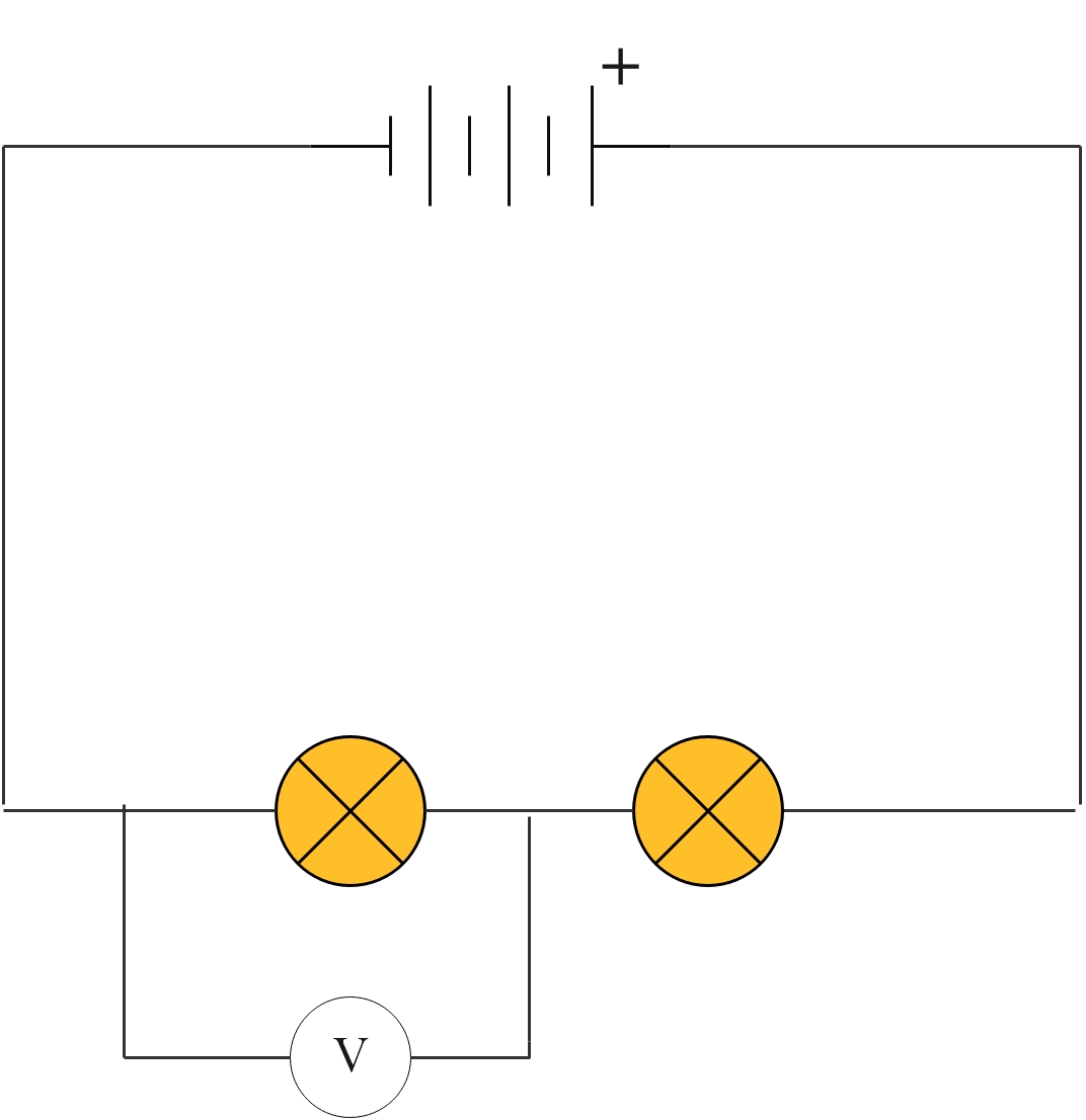
What is the reading on the voltmeter?
3. Move the voltmeter to the other lamp and measure the voltage through that lamp.
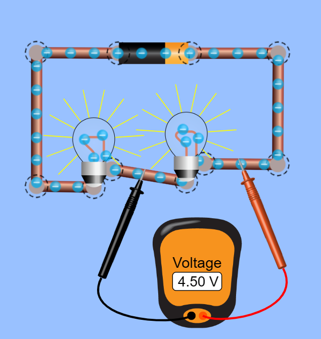
The total voltage across the lamps equals the voltage across the cell.
Ohm's Law
As previously mentioned, adding components to a circuit will resist the current, and are therefore called resistors. Resistors try to stop the current from flowing. Every material around the world has resistance for electric current.
Some materials have small resistance, called conductors, whilst other materials have very high resistance, called insulators.
Ohms law states that the current flowing through a metal wire is proportional to the potential difference across it, providing the temperature remains constant.
So, if you double the potential difference, the current is doubled.
The thin wire in a bulb will resist the movement of electrons in it. The greater the resistance, the more voltage is needed to push a current through the wire.

A current of 3 A flows through a 240 V lamp. What is the resistance of the lamp?
Resistance = 240 ÷ 3 = 80 Ω
A 2 V battery is connected to a wire with a resistance of 20 Ω. What current flows through the circuit?
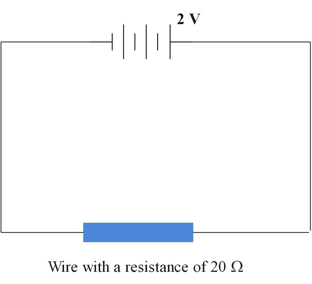
V = I x R
2 = I x 20
The current = 2/20 = 1/10 = 0.1 A
Resistors are used in a circuit to reduce the current. A variable resistor or rheostat is used to vary the current in a circuit. The volume control on a radio is a rheostat as is a dimmer switch on lights.
Activity 2
1. Click on the link below:
https://phet.colorado.edu/sims/html/ohms-law/latest/ohms-law_en.html
2. Using the sliders on the right-hand side, reduce and increase the voltage and observe what happens to the current and the resistance.
You should see that as you reduce the voltage, the current decreases. As you increase the voltage, the current increases. This makes sense because the e.m.f is what pushes the current around the circuit.
3. Reset the circuit. Using the slider on the right, decrease and increase the resistance and observe the effect on both the voltage and current.
As you decrease the resistance, the current increases. As you increase the resistance the current decreases. Any increase in resistance will slow down the current and visa versa.
Measuring resistance
Activity 3
1. Click on the link below:
https://phet.colorado.edu/sims/html/circuit-construction-kit-ac-virtual-lab/latest/circuit-construction-kit-ac-virtual-lab_en.html
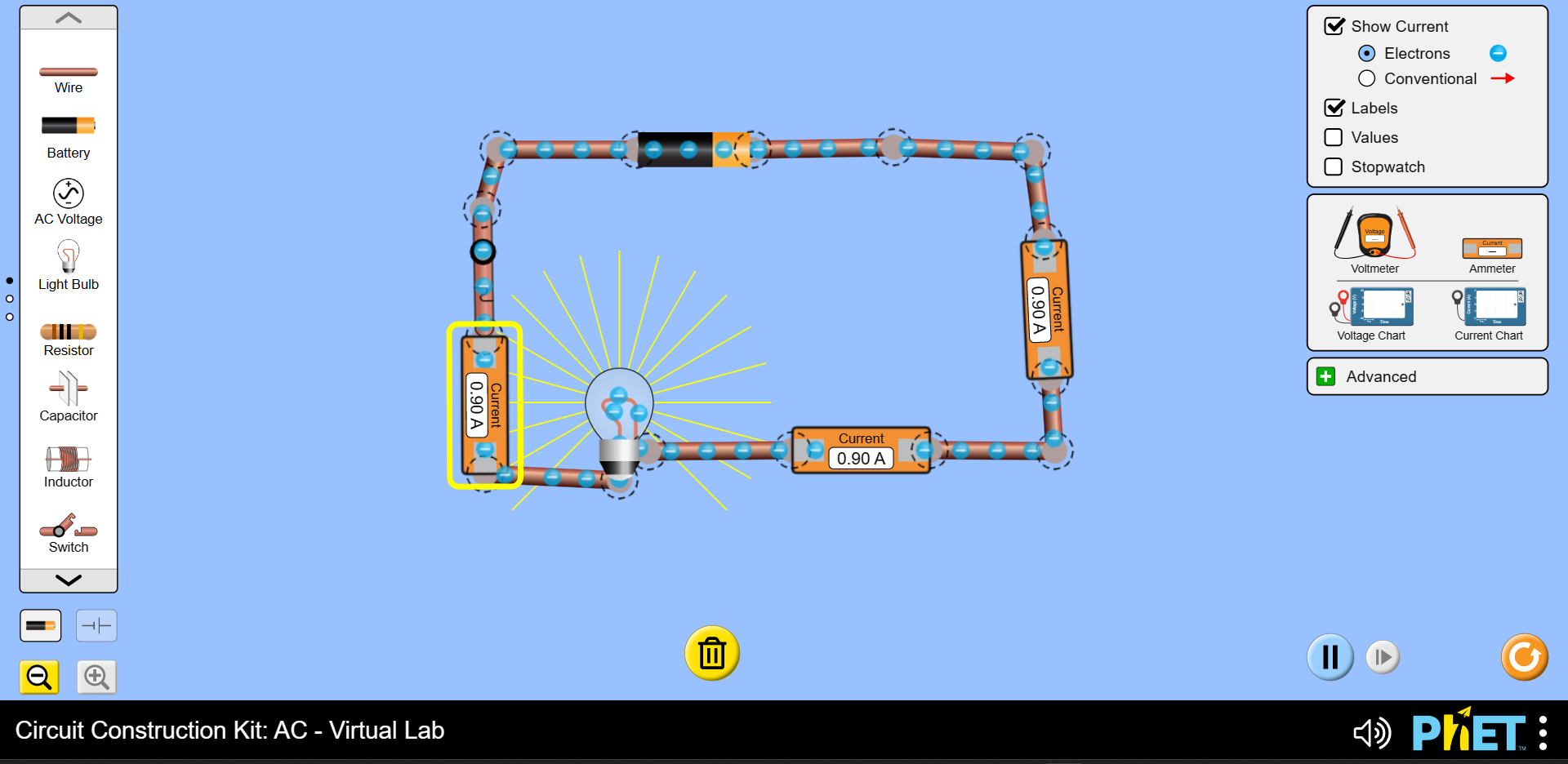
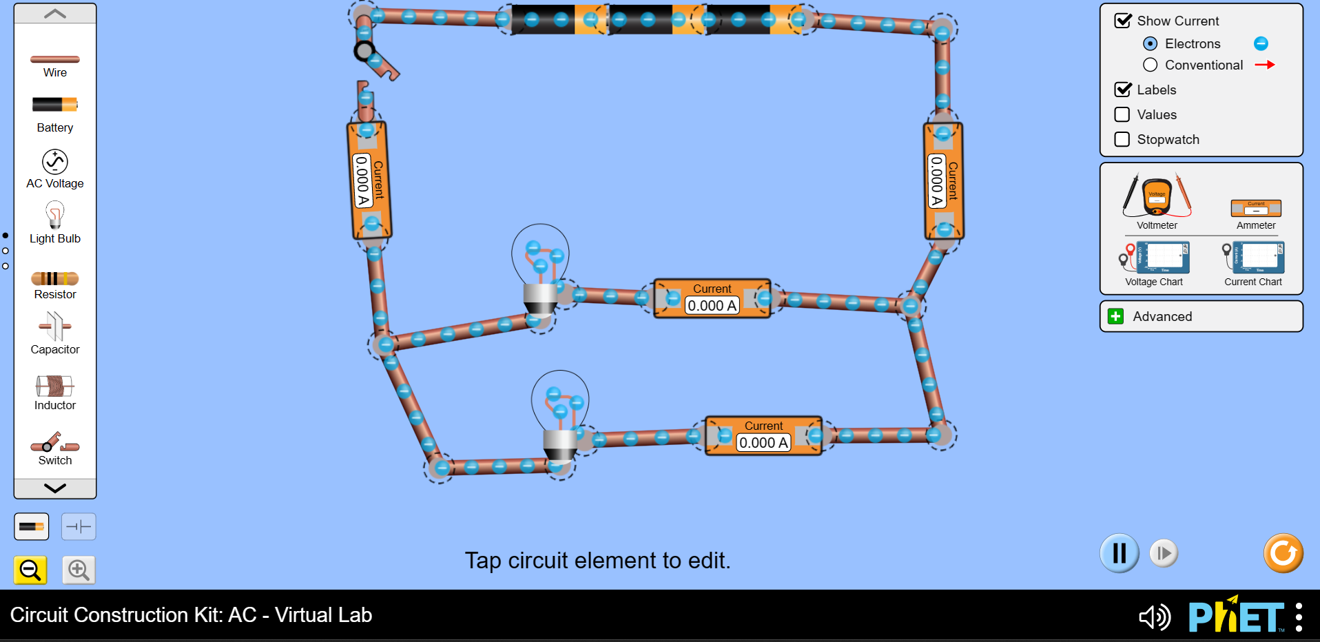
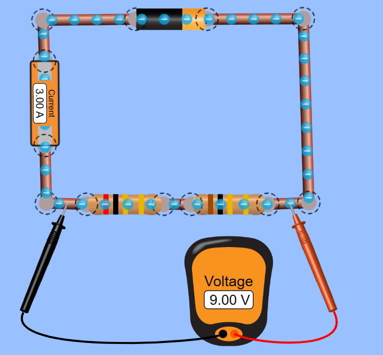
2. Build the following circuit:
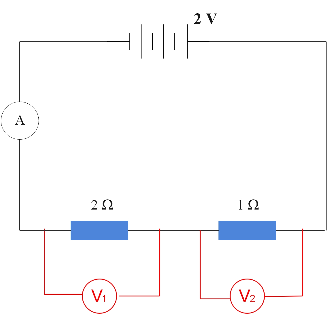
3. Tap on the resistors and set one as 2 ohms, and the second as 1 ohm. Place a voltmeter over the 2 Ω resistor and note the voltage.
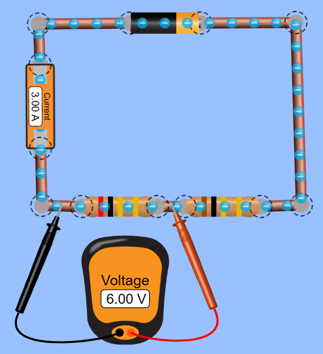
4. Place the voltmeter over the 1 Ω resistor and note the voltage.
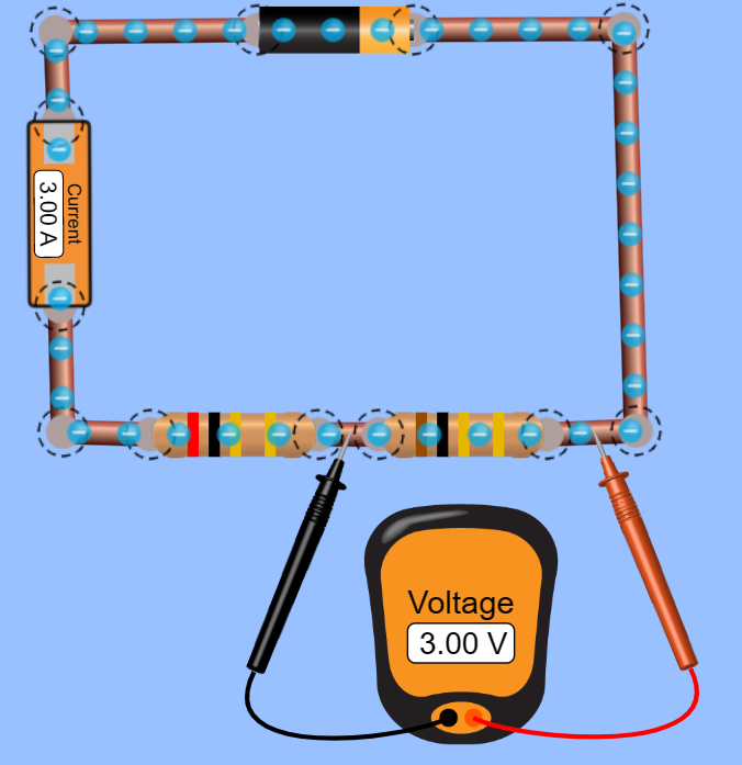
5. Place the voltmeter across both resistors and note the voltage.
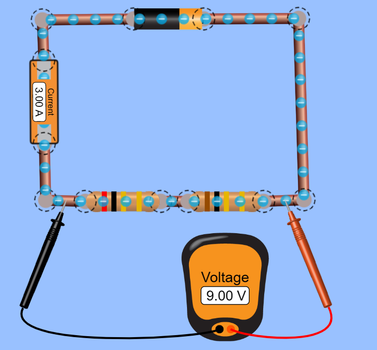
The total potential difference is the sum of the potential difference across the separate resistors.
V3= V1 + V2
For the above circuit, the total potential difference is 9 V.
The total resistance of a series circuit is equal to the sum of the separate resistance:
R = R1 + R2
So the resistance for the above circuit is:
2 + 1 = 3 Ω
